Designing the suspension components of the 2019 Formula SAE car has been a real challenge. I stepped out of my comfort zone of the powertrain systems and branched out into the chassis systems. This decision was largely based on my prospects of delving into vehicle design for electric vehicles. The suspension components mainly consist of the uprights and hubs, however this year I was able to design the team's first custom wheel center and also take over the design of the control arms.

2019 corner assembly rendering
|
The main goals of the 2019 design were to:
1. Lose one pound of mass 2. Reduce camber compliance to a tolerance of 0.3 degrees 3. Reduce toe compliance to a maximum of 0.03 degrees My plans were to remove mass from the uprights and to design lighter wheel centers. The wheel centers were changed from a four-lug design to a three-lug design to save weight as well. The projected weight savings amounted to 1.3 pounds, and even a little bit of weight loss helps. With the additions of more aerodynamic devices, it will be necessary to lose as much weight as possible. The camber compliance goals was determined by tire data that shows that grip is not significantly affected within 0.5 degrees of camber compliance. Toe compliance is very sensitive and can affect tire performance significantly if not minimized. |
Upright Design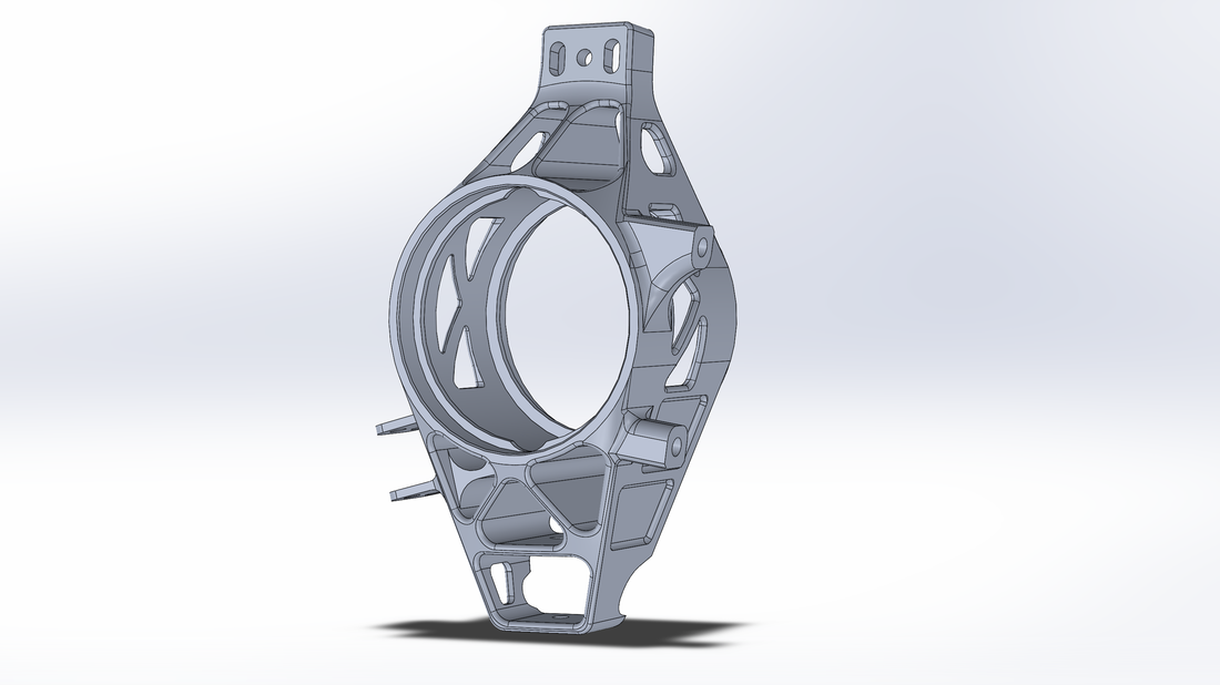
Using a bearing force calculator, I was able to estimate loads applied to the bearing races on the upright. I collected data from 2018 of the vehicle's longitudinal and lateral G-forces and derived the bearing loads from them. I compounded this data into multiple worst-case scenario situations where the wheel may experience high longitudinal, lateral, braking, and cornering forces. The bearing loads were collected for each scenario and a FEA program was run on the uprights to evaluate the stresses and factors of safety for each scenario.
|
Wheel Center Design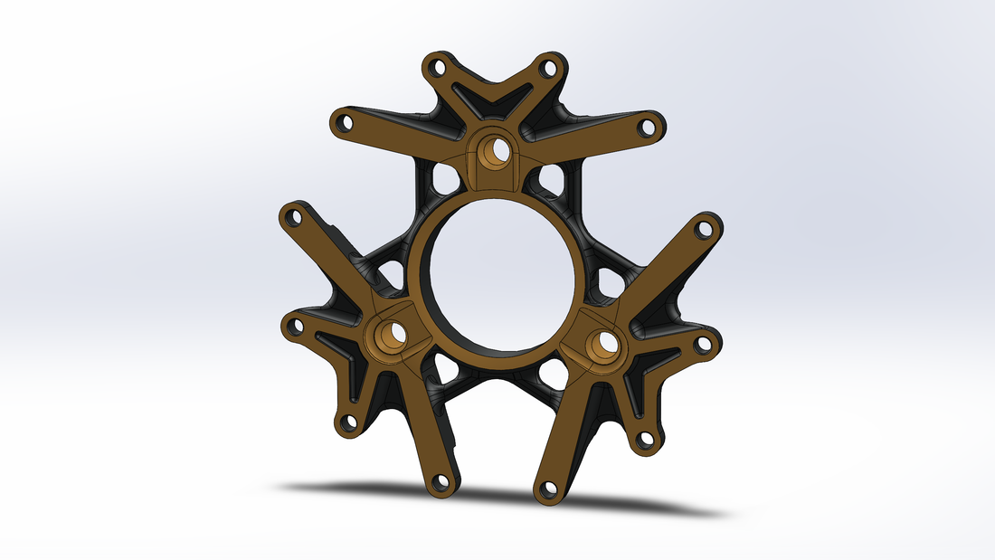
The wheel centers were designed using Altair's Inspire solidThinking software. By applying braking and cornering forces, I was able to create a lightweight and stiff wheel center that cut 0.2 pounds each. The model was further evaluated in Solidworks FEA simulations where the wheel center was subject to identical braking and cornering forces. The same process was performed for the 2018 wheel centers that came from Keizer. The 2019 wheel centers had noticeable improvements in stiffness and strength than the Keizers.
|
Factor of Safety*
|
Total Weight Loss
|
Factor of Safety*
|
Total Weight Loss
|
*This factor of safety was determined by fatigue strength, not yield strength. Fatigue strength was determined to be 43 ksi according to the high-life cycle of 5 x 10^8 cycles for aluminum.
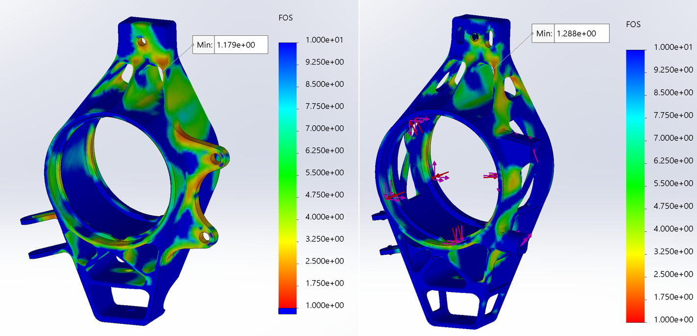
(Left) 2018 front upright FEA of fatigue factor of safety. (Right) 2019 front upright FEA of fatigue factor of safety.

(Left) A blank wheel center with the appropriate fixtures and design spaces.
(Center) The wheel center after the optimization simulation.
(Right) The wheel center modeled in Solidworks.
|
The bearing load calculator uses acceleration forces (G) to calculate the bearing loads seen by the two upright bearings in each upright. The parameters required are the vehicle and driver weight, downforce, kinematic and suspension setups, and bearing properties. The acceleration forces are determined from data acquisition of the center of mass acceleration forces. For the 2019 calculator, the longitudinal, lateral, and bump forces are extracted from Lincoln 2018 data from dynamic events. The maximums of these three forces were recorded for each dynamic event within the calculator. These scenarios can then be selected to use for each load case of the suspension components.
In order to get a better idea of the improvements made to the 2019 uprights, the same FEA simulations were used for both the 2018 and 2019 uprights. This was done to verify the 2019 design based on the 2018 performance. Here is a list of the FEA results: 
Once the design was finalized, the components were prepared for manufacturing. I created a drawing that LSU machinists would use to fabricate these parts on CNC mills and thus, must be made with accuracy and clarity. Below you can find a PDF of the drawing I created for manufacturing the 2019 suspension components.
|
|
On the right, the wheel centers have been successfully manufactured. Once all the components have been manufactured, they will be assembled and then under go verification testing. This testing will validate the goals set initially for camber and toe compliance.
A jig will be designed to hold a corner assembly facing down and weights will be hung from the toe link mount. A dial indicator will be used to measure the bending deflection. A similar process for the camber compliance test will be performed where the jig will hold the corner assembly at a normal orientation and weights will load the inside face of the upright to simulate camber loading. A dial indicator will be used again to measure the deflection. |

The 2019 wheel centers
|
