|
I am a part of Team #28, the Formula SAE Advanced Aerodynamics Package team. Our objective as a team is to produce an advanced aerodynamic system with te implementation of side wings and an undertray. By optimizing these new developments with the existing front and rear wings, the aerodynamics package can produce a projected 320 pounds of aerodynamic downforce, which is a 60% increase from 2018.
My main role on this team is a solid modeler and stress analyst. I support the computational fluid dynamics (CFD) analysis team with models that they use in their simulations. This is an integral part of working in a cross-disciplinary team. Being able to understand the CFD software and the required parameters is essential to quick turnaround time in design revisions. Along with a couple other team members, I was also responsible for creating the manufacturing files necessary to fabricate our parts and generating technical drawings for the machinists.
|
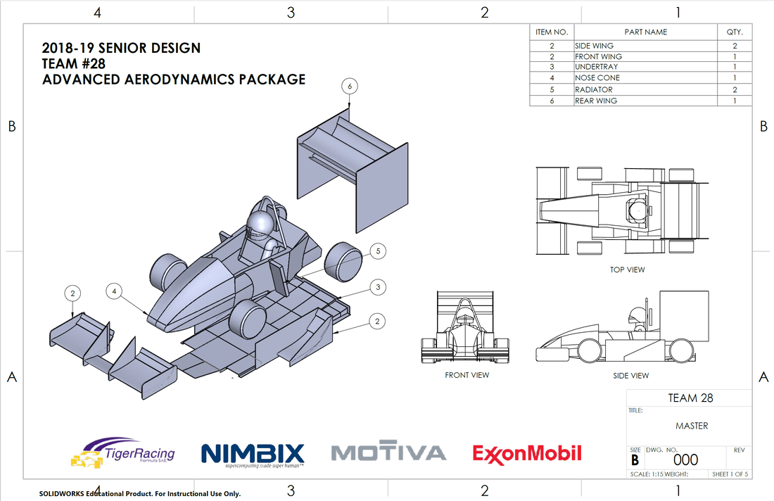
Final assembly drawing (December 2018)
|
|
Airfoil Core Design
My first project on the team was to design airfoil cores that were lightweight and stiff. Our advisor had suggested we used the carbon-nylon 3D printers that were newly available at the time. I set off using Altair's Inspire solidThinking software to design an airfoil core that could withstand the highest skin pressure, which was actually during the carbon layup process when subject to a vacuum pump. The pump can exert a pressure of roughly 30 psi and so the cores were designed with that in consideration. Using the solidThinking software, I was able to generate a topology optimized structure for best stiffness performance. This would consider deflection in the airfoil during operation, which was investigated using finite element analysis (FEA) to estimate the deflection magnitude and location on the airfoil core. The generated structure was used to create a lighter solid model that was then 3D printed. The results of the design were less than ideal, arriving to an extremely stiff core but the weight was much higher in comparison to cores made of foam. |

Design notebook excerpt of the airfoil core design (October 2018)
|
Mounting Component Design
The main project I took on was to design mounting mechanisms for the aerodynamic devices. I went into researching potted inserts, a commonly used fastener in aerospace applications. Potted inserts were lightweight and flush to the surface, which was more ideal can nuts and bolt heads protruding from these aerodynamic surfaces. The first objective was to determine the necessary strength of these inserts.
The main project I took on was to design mounting mechanisms for the aerodynamic devices. I went into researching potted inserts, a commonly used fastener in aerospace applications. Potted inserts were lightweight and flush to the surface, which was more ideal can nuts and bolt heads protruding from these aerodynamic surfaces. The first objective was to determine the necessary strength of these inserts.
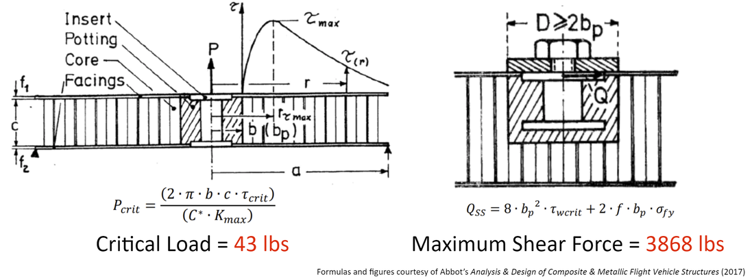
Critical axial load and shear stress distribution curve of potted inserts
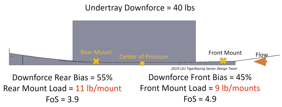
Undertray mounting strength analysis
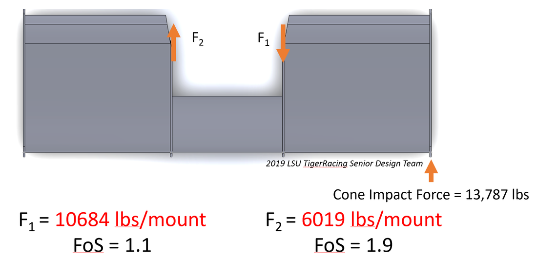
Front wing cone impact analysis
|
I used hand calculations to estimate forces seen from multiple worst-case scenarios: cone impact and crash impact. Cone impact can happen on the track and the potted inserts must not fail, however they can fail in the event of a head-on collision where the front wing should break off to allow the impact attenuator to absorb the crash forces. As seen on the left, I used a potted insert strength calculator to determine the yield strength of the inserts and found a safety factor when comparing it to downforces on the mounts and the estimated impact forces. The undertray was projected to produce 40 pounds of downforce, and in axial loading, four potted inserts were capable of holding the load. I found that at a track top speed of 60 miles per hour, the potted inserts were also able to withstand a worst-case scenario cone impact on the outside edge of the wing. This would cause the largest moment on the wing mounts and designing them to withstand these forces would mean reliable operation and reduce the risk of failure. I intend on implementing these potted inserts and performing a series of physical tests to determine their viability. With these composite inserts, we can lose weight by replacing the previously used heavy steel fasteners. If you would like to learn more about this project, please read the full design report below. |
