The first step to reducing the weight of the motor is by taking out unnecessary gears. In the competition's dynamic events, the team rarely ever reaches fifth and sixth gear. So to shave off as many pounds as I could, I physically removed the previously mentioned gears from the main transmission shaft. Removing these gears and the parts necessary to hold them there will save us 0.415 kg or 0.915 lbs.
Now, motorcycles gearboxes have constant mesh gears. These gears always remain engaged with gears on the other shaft. Sliding dog gears with dog "ears" are shifted from side to side to interlock with larger gears in order to change gear ratios. Since I removed fifth and sixth gear, I can also make a modification to the gears that engaged them on the counter shaft. I plan on machining the gear teeth down since they are not necessary anymore for engagement.
I modeled the gears in Solidworks and after specifying the correct material (AISI 4340, hardened steel) I used Solidworks' feature, Mass Properties, to find the mass of the gear and then verified that number by placing the gear on a scale*. I then cut away the gear teeth on Solidworks and then used Mass Properties again to find the weight after the modification, and from that found the weight difference. Using this method, I found that machining both dog gears involved with the engagement of both fifth and sixth gear will save approximately 0.804 kg or 0.192 lbs.
*I implemented a 10 g tolerance. The difference found in Solidworks and in actuality would be proportional so that the difference is approximately equal.

|

|
In order to make sure that machining the teeth would have no effect on the structural integrity of the gear itself, I ran a Finite Element Analysis in Solidworks on the dog gear. I placed a torque of five pound-feet on the side face of each dog ear in a counter clockwise direction. This mimics the rotation that the transmission will be spinning. I ran three FEAs on three different versions of the dog gear: unmodified, one millimeter grind, and a flush grind. The tensile yield strength of AISI 4340, hardened steel is 786 MPa. In this FEA, only a maximum von Mises stress of 0.322 MPa on the one millimeter grind was to be found. This tells me that grinding the teeth will have virtually no effect on the gear's structural strength.

An FEA of the C5 gear
|

An FEA of the C6 gear
|
|
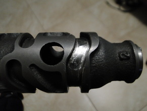
The team ran into many shifting issues where the driver would accidentally shift into neutral gear resulting in no acceleration. The way a motorcycle transmission is designed is first gear, neutral gear, second gear, and so on until sixth gear. So to prevent the accidental shift into neutral, I studied the shift drum, a cylindrical part with slotted pathways wrapped around the face (as seen in the image to the right). Shift forks with nubs slot into those pathways and so as the fork follows the shift drums path, it moves left and right. These forks fit in the dog gears and shift them into position as they move left and right.
One particular shift fork fits into the M3/4 gear. This is double sided dog gear slides between M5 (sixth gear) and M6 (fifth gear). Since, fifth and sixth gear are no longer in the picture, the shift fork for M3/4 is no longer necessary, saving us 0.087 kg or 0.192 lbs. In order to restrain M3/4, we will machine two snap ring grooves into the main shaft since the shift fork is no longer restraining the dog gear. However, we cannot take out the M3/4 gear because it still remains engaged with gears on the counter shaft.
|

|
Now in order to tackle the accidental shift into neutral issue, I decided on a plan that would prevent this from happening. The shift drum has a shift star, a piece necessary for the shift drum to rotate exactly 60 degrees every shift, except for one "point" of the star. One of the "points" is cut lower, with circular well for the stopper wheel to fall into. This is the half shift, the point from first to neutral.
The star has a slot on the back in which a pin on the shift drum's metal face sits in. This locks the position and ensures that the orientation of the star is correct. If we were to machine a now slot for this pin, we could rotate the star so that we relocate where the half shift is, preferably where fifth and sixth gear would originally be. However, placing it here would result in neutral being at the end of the shift pattern. So, I plan on machining the shift drum so that a downshift from first gear and have us sit in neutral.
To do this, I machined the left pathway end (via a lathe with live tooling) and had it meet the other end so that the left pathway is continuous. This will allow that shift fork to travel counter-clockwise, shifting the gears into neutral.
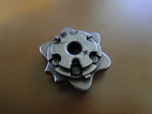
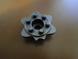
This is the shift star (front and back). Notice the circular well where the stopper wheel will fall into for half shift. A full shift is when the stopper wheel will roll over one "point" of the star. Also, notice the hole drilled out from the bottom. This is where the pin sits.
|
|

One of the three shift forks. Notice the nub that fit into the pathways on the shift drum. The wishbone curve is where the fork fits in the dog gear.
|
